| S-Video |
| S-Video in an interface that carries luma (black and white) information and chroma (hue and saturation) information on separate wires. This interface is free from the cross color and cross luminance of conventional NTSC composite multiplex. |
| This modification gives the GR-295 a composite input and accesses the luma and chroma inputs of the GR-295 separately so the set can display S-Video sources to full advantage. |
| The schematic is simple enough to follow. Heathkit designators are used for all original components. A switch reconfigures the circuit from the original receiver format to the composite input or S=Video input. Diode DC restoration is also added. This is shown as the new circuitry around the brightness control and the diode across R408. The DC amplification of the output pentode is stabilized by the zener regulator on the screen grid and blanking is improved by the transistor in the cathode circuit. This is similar to the circuit in the GR-681 but with improved reliability. The RGB drive circuit is also improved with more stable DC on the dividers. The circuit was constructed on a Radio Shack board that matches the layout of a plug in prototype board. None of the wiring or layout is critical. |
|
| How well does circuit work? Picture quality is excellent from composite and S-Video sources. |
| The set's delay line is the component that most limits the horizontal resolution. With an improved delay line, the horizontal resolution of the modified GR-295 is over 500 TV Lines. |
| See my delay line page for how to make high quality delay lines. The GR-295's original delay line is marked Heath part number 41-1 and Belfuse 1118-12. Its response to a 100 kHz square wave is shown in the first photo below. The improved delay line's response is shown in the second photo. |
|
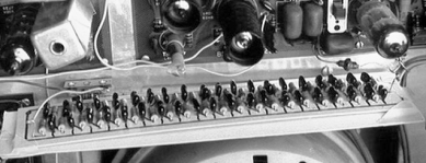
| The original delay line is a distributed parameter line that is a coil of wire on a cylinder with a strip of foil on one side. The coil is the inductor. Each time the wire passed the foil there is capacitance. The replacement delay line is descrite inductors and capacitors. The photo shows the delay line inside the GR-295. |
|
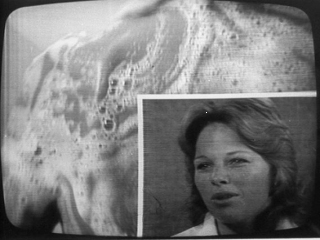
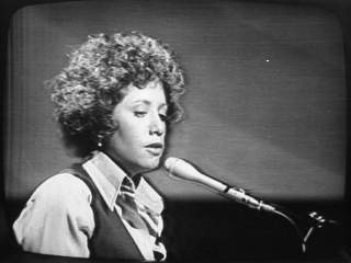
| Two off air pictures illustrate the delay line modification's results. In the soap commercial note the vertical dividing line looks the same as the horizontal dividing line. There is no visible overshoot or ring at the left or right edge of the vertical line. Most TV sets show these defects. In the other photo, note the completely natural look of the curvature of the singer's face, hair, and blouse. There are no distracting offsets, outlines, or ringing. Those defects made the image look flat on the unmodified set and most TV sets. The dark outline at the right of her face is the background color, which in NTSC color is of low resolution. |
|
| For more information on the design of this delay line see my delay line page. |
| This set was in daily use until 2002 when the picture became unacceptably dim. |
Send questions or comments on this page to David Carlstrom.