|
TV sets using the traditional NTSC bandpass demultiplex scheme require a delay line to make the wide bandwidth luma signal arrive at the screen at the same time as the color signal that is delayed by its narrow bandwidth filters. The delay of that processing is about 1 millisecond. The usual solution is a distributed parameter line in the luma amplifier. These are made by winding a coil of wire on a cardboard cylinder about a half inch in diameter and about six inches long. Outside the coil and insulated from it is a strip of foil. The coil forms the inductive part of the delay line. Each time the wire passes the foil strip there is capacitance. Thus the delay line is like a sequence of LC sections. More accurate delay lines can be made from discrete inductors and capacitors.
|
| The lumped parameter delay line consists of a series of low-pass LC filters. The delay, t, in Seconds for n sections is given by
|

|
|
where t = delay in Seconds, L = inductance in Henrys, and C = capacitance in Farads.
|
|
The characteristic impedance is given by
|

|
|
The cutoff frequency is
|

|
|
My reference is an ancient text book, Electronic Circuits and Tubes, by the Electronics Training Staff of the Cruft Laboratory, Harvard University, McGraw-Hill Book Company, Inc., New York, 1947.
|

|
|
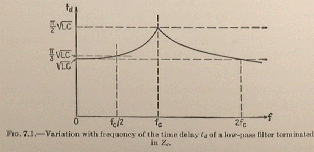
Delay is 57% greater at cutoff than at low frequencies. Delay is within 5% at half that. This is shown as a graph in the Cruft book.
|

|
| The impedance of the delay line in the vacuum tube GR- 295 is about 1500 ohms. I selected 15 pF capacitors and 33 uH inductors for a delay per section of 22 nanoseconds and a cutoff frequency of 14.3 MHz. This delay line should be with in 5% of the calculated delay at all frequencies up to 7.1 MHz. The initial estimate was 49 sections for a total delay of 1.1 microseconds. Measurement of color fit on the screen suggested a longer delay would be more accurate. The final delay line has 53 sections.
|
| The GR-2000 delay line is about 560 ohms. I selected L = 10 uH and C = 22 pF for a delay per section of 14.8 nanoseconds accurate within 5% to 10.7 MHz. The initial estimate was 60 sections for a total of 0.81 microseconds. Best color fit from an S-Video input was with 57 sections.
|