| Issue |
| Televsion sets typically apply the video signal to the CRT cathode(s)) in the range of 150 to 250 Volts above ground. The CRT filament is typically supplied from a transformer winding. In the better designs this winding is devoted to the CRT and biased to about 200 Volts DC to minimize the voltage stress on the heater to cathode insulation. One failure mode is that insulation breaks down. It is also possible for the power transformer to develop leakage. Any leakage may attenuate or bias the video signal. In the early days of television isolation transformers were available to add another layer of insulation, making the leakage in the CRT of the set's power transformer. My GR-2000 seems to have both leakage paths, heater to cathode, and within the power transformer. |
| Solution |
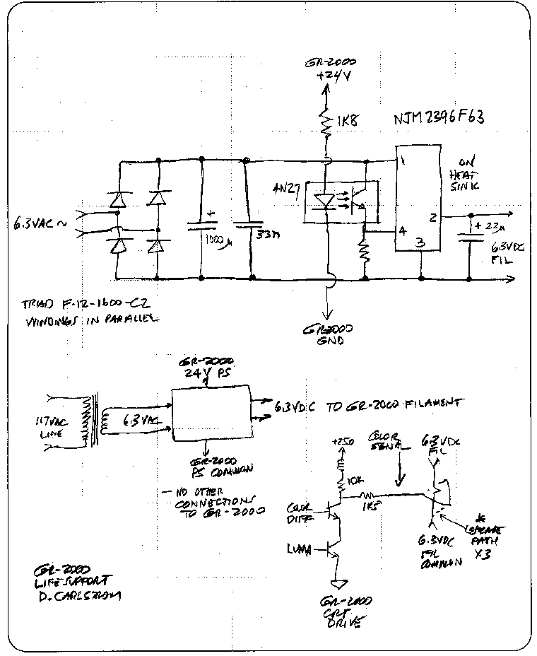
| I could not find a suitable filament isolation transformer. A totally separate filament transformer would satisfy the CRT requirement, but there is no place in the GR-2000's circuit to connect the primary, due to the 'instant on' CRT power control system. Since it is also a good idea not to power the CRT filament with AC, as that can leak into the video, I searched for and found a DC voltage regulator that can be turned off and on by a control signal. |
| The schematic is simple enough to follow. The television's main DC power supply (24 Volts) is applied to the led of an opto-isolator, which controls the NMJ2396 low drop regulator. This chip is available with a fixed 6.3 Volt output, exactly matching the CRT's requirement. Thus when the TV is turned on the 6.3 VDC becomes active. |
|
| How well does circuit work? The picture is free of biases and free of hum. |
Send questions or comments on this page to David Carlstrom.