| Time Division Multiplex Color TV |
| It is easy to look back in history, to point to weaknesses, call some things wrong turns. One might be CBS Field Sequential Color; RCA Dot Sequential Color another; but weaknesses in these lead to solutions that became the NTSC Color Standard, legitimized in 1953. It is most used, most maligned, simplest and best color TV standard. This page looks back at Dot Sequential Color, an Essential Wrong turn in the History of Color TV and includes a details of a modern day demonstration circuit. |
| Trying to make time division multiplex send three image signals to the receiver using straightforward sampling at three dots per pixel won’t fit in the channel bandwidth defined in 1940 for black and white TV. RCA came up with a scheme using fewer dots plus a scheme to retain adequate resolution. |
| Inspiration for this page came from RCA Engineer George Brown’s autobiography (1) and from Microsoft Scientist Jim Blinn, who was at Cal Tech at the time (2) . Brown wrote that the first RCA switching receivers could receive the final form of NTSC with no modifications. I pointed out Brown’s claim to Blinn and he confirmed it. He wrote that NTSC was “...just about like multiplying R, G and B by raised sine waves out of phase by 120 degrees and adding them up.” |
| RCA was trying to create an in-band time division multiplex scheme, where the color information was in the same frequency range as the existing black and white values. The idea was to multiplex three signals in the space allotted for the one signal for B&W, create monochrome TV times three, but stay in the existing channel. CBS used mechanical sampling which of course was relatively slow. RCA used electronic sampling. CBS's scheme had a low rate sampling of 120 Hz. and later 144 Hz. RCA strove for the highest possible sampling rate, trying to be close to the channel's upper limit of 4.2 MHz. |
| RCA's scheme was called “Mixed Highs". It combined low resolution color and black and white details. The idea was to transmit samples of color in the sequence red, blue, green. Sample each color at a 4 MHz sampling rate, after a low pass anti-aliasing filter at 2 MHz. Then add to that high resolution details above 2 MHz. to make a composite signal. The concept of not needing full resolution for each color was soundly based in the science of human vision. The scheme seems to make sense. See the small illustration for a simple image showing the red signal, filtered, the blue signal, filtered, the green signal filtered, the details signal, and the combined signal. |
|
| The main issue is the fact the sampled signal bandwidth is over 3.8 MHz; it overlaps the monochrome detail signal. What should the filter slope be? There are probable cancellations and missing frequencies. First order filters yield poor band separation and inadequate anti-aliasing. It is not obvious how to overcome these issues. The solution came from mathematicians at Hazeltine, who viewed RCA’s system as described above in the frequency domain. The fixes make sense in frequency domain. The signal added to black and white is called the Color Subcarrier which is Quadrature Modulated Double Sideband Suppressed Carrier. With that Dot Sequential became NTSC. I think the main addition was better filters. |
| An NTSC de-multiplex circuit is complex. It needs a crystal, a 3.1 to 4.1 MHz bandpass filter, phase shifters, inductors, and a delay line, Dot Sequential de-multiplex appears simpler. The crystal is still needed. Beyond that only a switcher and reconstruction filters are necessary. My experimental design wound up being not so simple! It has 5 Video Op Amps and 9 CMOS Chips. |
| The experimental demux circuit blocks are: Recover Burst; Synchronize Local 3.58 MHz Oscillator to Burst; Generate Sampling Gates; Triple 3.58 to 10.74 MHz; Create Three Gate Signals; 120 Degrees of a cycle of 3.58 MHz is R, B, then G; Low Pass Filter Each Signal. The low pass filter is not quite to the mixed highs concept. It low pass filters each signal at 4.2 MHz. RCA said to reconstruct the colors at 1.79 MHz, high pass the composite at 1.79 MHz and add the details to the color signals. Would it work better than the experimental circuit? With 1st order filters, I doubt it! |
| The schematic is simple enough to follow. Straight across the middle is the composite signal going to the three choppers and outputs. At the top is the 3.58 MHz oscillator and tripler. At the bottom is the sync separator. In the center is the burst gate. The schematic image is not of adequate resolution to be read. A .cad version is available for the asking. |
|
| How well does demo circuit work? The colors are very slightly off. 120 degrees each may not be exactly the right solution. There are rainbows on details. There are lots of dots and dot crawl. It might be better if filtered as RCA described, but that could not be as good as conventional NTSC bandpass demux. I believe the frequency domain view, the conventional band pass filters are best. |
|
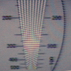
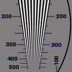
| The enlarged views show one aspect of the performance of the dot sequential demux. Dot sequential demux is on the left. Comb filter demux is on the right. Note the cross color (the dots) and cross luma (the rainbow effect) in the dot sequential picture. The comb filter is a direct connection from a DVD player to a Matrox RT2000 video editing card, so it represents the best possible image. The dot sequential picture was taken from a monitor screen. |
| This web page is a version of a talk I gave at the Early Television Convention. |
| For additional information on dot sequential color television see Ed Reitan's RCA Dot Sequential Color System web page. |
Send questions or comments on this page to David Carlstrom.