Field Coil Loudspeakers

Neodymium, ferrite, and alnico are all relatively recent developments in speaker magnet technology. Prior to the development of these permanent magnets, the dominant speaker magnet technology was an electromagnet. The speaker magnet structure was iron with room for a coil of copper wire. A direct current through this coil provided the magnetic field for the speaker. In household radios and phonographs, the power supply current for the vacuum tube circuit of the unit passed through the speaker's field coil. The coil thus served as a power supply filter choke as well. Engineers designed the number of turns on the field coil, the gage of wire and the current to provide the required amount of magnetic flux in the speaker voice coil gap.

.


I wanted to know how strong the magnetic field was in this type of speaker. Is the electromagnet comparable to today's speaker magnets or stronger or weaker? I was able to borrow two electrodynamic speakers from Mark Oppat's Old Radio Parts inventory and measure their electromechanical and Theil/Small parameters.

One of the two eight inch speakers had the familiar name Jensen and the other was branded Rola. Mark was familiar with Rola and suggested it was the better speaker. The Rola electromagnet is larger and heavier than this Jensen. Both have thin paper cones and the outer suspension is formed from the cone paper not a separate material. This paper roll is more flexible than it looks. Both speakers had a modest amount of glue to fix small cracks in the cone and surround. Mark recommends hard glue for the body of the cone and rubber cement for the surround. The Jensen has a conventional looking formed cloth spider and a felt dust cap. The Rola has no dust cap and the spider has a shape matching the name "spider". It appears to be cut from a phenolic sheet in one piece. It has two legs that are flat in one plane. The center is attached around the voice coil form. The legs curve out to two mounting screws on the frame. The screws permit slight adjustment of the radial centering of the coil in the magnetic gap. The voice coil can be seen past the legs of the spider. This speaker has no means to prevent small metal chips from being attracted to the magnetic field in the gap. Each speaker had a transformer mounted on it. It a radio or phonograph the primary would be connected to the plates of the push pull output tubes. These speakers have an small additional coil around the electromagnet and in series with the voice coil. This coil is polarized to cancel hum from the ripple in the field coil. For testing, the connection to the secondary of the voice coil was opened and test connections tied directly to the voice coil, by passing the hum bucking coil.

In spite of the Jensen appearing to be protected from external metal particles entering the magnetic gap around the voice coil, both speakers sounded if there were chips in their gaps, when stroked with low frequency sine waves, but the effect was not noticeable on music. Both speakers played very loudly in a preliminary check. While the sound suggested some peakiness due to the thin cones, the overall sound quality was very good. Even in free air there was no lack of bass. The measurements confirmed the sensitivity is high.


EM and T/S Parameters Rola Jensen Modern Speaker
Effective Cone Diameter 16 cm 16 cm 16.8 cm
Maximum Linear Excursion, Xmax 2 mm (est) 2 mm (est) 5 mm
BL Product 3.47 N/A 2.77 N/A 3.64 N/A
Voice Coil Resistance, Re 2.15 Ohms 3.09 Ohms 1.93 Ohms
Moving Mass, Md 9.28 g 7.25 g 19.79 g
Mechanical Compliance, Cms 0.44 mm/N 0.26 mm/N 0.39 mm/N
Mechanical Losses, Rms 0.33 kg/s 1.15 kg/s 1.53 kg/s
Effective Cone Area, Sd 201 sq.cm 201 sq.cm 222 sq.cm
Resonant Frequency, f0 78.5 Hz 115.7 Hz 57.3 Hz
Equivalent Volume, Vas 25.4 l. 14.9 l. 27.2 l.
Mechanical Q, Qms 13.8 4.6 4.7
Electrical Q, Qes 0.82 2.1 1.04
Total Q, Qts 0.73 1.45 0.85
Reference Efficiency, n0 1.44 % 1.05 % 0.47 %
Output SPL 1 Watt 93.6 dB @ 1.47 V 92.1 dB @ 1.76 V 88.8 dB @ 1.39 V
Output SPL 2 Volts 96.3 dB @ 1.86 W 93.3 dB @ 1.29 W 91.9 dB @ 2.07 W

The Rola has a 900 Ohm field coil and was operated at 100 mA DC for the test. The Jensen has a 1600 Ohm field coil and was operated at 66 mA for the test. Current was supplied from a regulated bench power supply capable of 130 Volts. The Jensen required nearly that maximum voltage. This represented a substantial loss of power supply voltage for the radio which had to be made up in its power transformer design.

The Rola has a heavier cone, but s higher BL, and at 1.4% is more sensitive than the Jensen. The field coil of each speaker was drawing enough current to get warm. The heat was enough to change the resistance of the coils. For testing, the DC power supply voltage was adjusted to keep the current constant. In actual use the sensitivity and Q might vary with the temperature of the field coil.

The same data is listed for a modern speaker of about the same cone area. This speaker is a car audio 6" x 9". It is intended for car door applications, which are more baffles than enclosures and thus resemble the usages for the Jensen and Rola. The modern speaker is remarkably like the Rola, except for cone mass, which is double and Xmax which is nearly double. These account for the lower sensitivity of the modern speaker. The heavier cone is what gives the modern speaker smoother frequency response. The larger Xmax makes the modern speaker have less distortion at higher outputs.


A few readers of this page have a field coil speaker and have asked how to make it play.

To use one of these field coil speakers, apply a DC current to the field coil. The current I used is about what you will need, but each speaker will be different.


Field Coil Power Selection Resistance Current Voltage Power
Rola 900 Ohms 0.100 Amperes 90 Volts 9 Watts
Jensen 1600 Ohms 0.066 Amperes 106 Volts 7 Watts
Your Speaker R =SQRT(P/R) =SQRT(P*R) P
Example 1000 0.100 100 10

First measure the DC resistance of the voice coil with an ohmmeter. Select an audio amplifier that can drive that impedance. Connect a permanent magnet speaker to the amplifier and play some audio at a moderate level. Stay below about one volt. Then connect the voice coil of the field coil speaker to the amplifier in place of the permanent magnet speaker. You may hear a faint amount of audio with no power in the field coil due to residual magnetism in the electromagnet. Connect your DC power supply to the field coil. Start with a low current. Increase the current gradually into the range calculated in the table above. Check that the field coil does not become too warm.

As you increase the current in the field coil, the audio from the speaker will increase. When it plays as loud as the permanent magnet speaker, you have enough current. If your field coil is becoming warm, you will have to reduce the current.

The level of bass at resonance does not change much with the field coil current. The level of the midrange and treble will be strongly affected by the field coil current. To some extent you can adjust the balance of bass to midrange to match your system needs with field coil current.

For more on the relationship of "B" created by the field coil magnet current and sensitivity watch Fresh Look at T/S Parameters on the SMWTMS YouTube Channel.

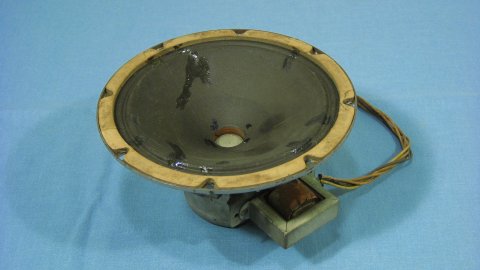
Historically a radio with a field coil speaker did not have a separate power supply for the speaker magnet. The field coil was used as a choke in the power supply for the entire radio. The field coil would be designed to use the total current of the radio. This is why you will find many different resistances on field coils. The substantial voltage drop in the field coil resistance was compensated for in the deign of the power supply transformer of the radio. In the examples on this page, the radio power transformer would be specified to have about 100 more volts than the radio needed. There would be some hum in the speaker, though that might be cancelled by the hum bucking coil mentioned at the top of this page.

Some inquires about this page asked if a field coil speaker could be used in a guitar amplifier. Obviously one can, but the external power supply for the field coil would be quite a bit to add. Tone quality of a field coil speaker in a guitar amplifier will depend on the field coil current. It might be interesting to use a variable DC power supply for the filed coil speaker in a guitar amplifier. Trying to add the field coil using the historical design as a choke in the power supply would cause a substantial loss of output power unless the power transformer was replaced as well.


Photographs text and graphs by David Carlstrom
Copyright October 15, 2011 Text updated May 18, 2020.
Send e-mail to David Carlstrom: david6040@yahoo.com

Web Page Created by David Carlstrom.
Last Modified: 5/18/2020