| History of the Close Ties between Movie Film and Video |
| The first theatrical showing of a motion picture in the USA is reported to have been on April 23, 1896. The first regularly scheduled television broadcasts were in 1937 by the BBC, and in 1940 in the USA. Throughout the history of the development of television, movie film sources were often used. Film gave repeatability for tests. Film compensated for the low sensitivity of early camera devices such as the Farnsworth Image Dissector and Zworykin's Iconoscope. There were many types of film scanners. Optical scanning could be done with continuously moving film and rotating mirrors. Hybrid scanning has continuously moving film and an electronic line scanner. The latter is used today in the form of a continuously moving film and a line array CCD. The system I will describe building is called a Film Chain uses a movie projector shining the image on a conventional television camera sensor. In the 1940s this was an iconoscope. Today I use a CCD video camera. |
| Movie Projectors |
| A movie projector works by intermittent movement of the film. Each frame is held still for projection. A shutter is closed when film moves, so the audience sees a sequence of still frames. In a film chain, the television sensor has to be arranged so it can raster scan whole frame while it is still. If the frame rates matched one to one, all that would be needed is synchronization. Some TV films are shot at 30 fps, but most movies are at 24 frames per second. To convert 24 fps film to 30 fps television, a system that has come to be called "3:2 pulldown" was developed. This assigns 2 film frames to 5 video fields ( each video frame has two fields). 3 fields come from one film frame and 2 fields from a second film frame. This uneven cadence can sometimes be seen in televised movies and has been given the name "judder". |
| Transferring Home Movies |
| Transferring home movies to home video adds more variables. Video is still at 30 fps, but small film runs at many frame rates. For 16mm there are standard speeds of 16 fps for silent movies and 24 fps for sound movies. Silent 8mm is sometimes 16 fps and sometimes 18 fps. Cameras were not exactly on speed and projectors had variable speed. Super8 standardized on 18 fps, but some sound movies on 8mm or Super8 film was shot at 24 fps. |
| A "wild" (non-synchronous) transfer, such as just aiming the video camera at the screen gives poor results. flicker varies from horrible to mild. A projector with the typical 3 blade shutter and a vidicon camera tube is really bad. A 5 blade shutter and a CCD camera gives only mild pulsations such as was seen on the PBS series on "Diners"). To avoid flicker there must be synchronization, but at what rate? |
|
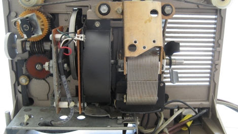
| My projector is stated to run at "fixed speed" of "18 fps", but it has a two pole induction motor and a rubber puck drive, so the speed can only be approximately that number. It has a 3 blade shutter, which gives 54 blinks per second. My idea was to run it a bit faster to raise the 54 blinks to 60, or one blink per video field. |
| Synchronization Method |
| To synchronize I had to compare the video with shutter and control the projector motor to get the projector shutter speed to match the video rate. I developed a variable frequency AC drive system for the existing induction motor. |
| Video Signal |
|
| To get the frame rate out of the video signal a LM1881 Sync separator chip extracted the vertical sync signal. I initially included an opto isolator to break potential ground loops. The first two stages were to be powered from the video camera. The potential ground loop did not cause a problem, so internal power was used as shown. The extracted vertical sync is fed to a pulse stretcher, a 4538 one shot yielding an approximately symmetrical 60 Hz square wave. An adjustable delay was included for getting exact phasing with projector shutter, but it was not needed with my CCD video camera as the storage of the CCD covered phase errors. The second 4538 is a sync detector. This signal will prevent the projector stopping if the video sync signal is lost, due to a failure or a loose cable. |
| Shutter Signal |
|
| The projector speed is detected at the shutter with an infra red LED and infra red detector at the shutter disc. The result is a somewhat square wave that is cleaned up with hysteresis and gain in an op amp. The phase detector, a 4046 PLL Chip, compares the shutter signal with the video 60 Hz square wave. The DC error voltage output is used to control the projector motor. The 4046 phase pulse output goes to a lock indicator and the lamp control relay. |
|
|
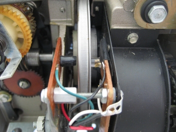
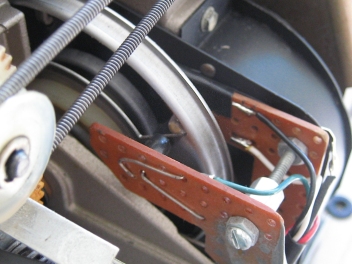
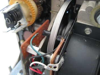
| Perfboard supports the IR opto detector and emitter on either side of the metal shutter. The IR detector has a black shield of shrink tubing. In the left photo note the shutter edge is aligned with the opto. |
| DC Error Amplifier and Protection |
|
| The error voltage goes to the DC servo amplifiers. The 4046 source follower output is buffered and low pass filtered and passed to an inverting adjustable gain stage. The diode from the sync detector one shot actuates the projector speed upon loss of the video sync signal. |
| AC Generator |
|
| A second 4046 PLL chip is used for its VCO. Its output is nominally 570 Hz (528 Hz to 616 Hz). This goes to a divide by 8 walking ring counter composed of two 4013. It has three square wave outputs at 120 degrees to each other at a nominal 74 Hz (66 Hz to 77 Hz). |
| Sine Filter |
|
| The three square wave phases are summed in an op amp to make a step wise sine wave. A low pass filter, 1st order in summing stage, plus 3rd order in the inverting active filter yields a low distortion sine wave. |
| Balanced Outputs |
|
| The sine wave is coupled to output buffers with a small capacitor to give an increase in voltage with frequency. This helps speed control of the induction motor which responds to both input frequency and voltage. One output is inverted. |
| Lock Indicator and Lamp Control |
|
| The Lock Indicator is a Red/Green Two Color LED. The drive is inverted to the red LED. The lamp control signal is filtered and delayed. The relay is in a surplus AC control box I sold several of at past SMWTMS trunk sales. It also serves as power supply for the servo circuits. |
| Modified Audio Power Amplifier |
| A Dynaco Stereo 120 was modified to improve its stability by taking feedback from amp only and none from the output terminal. Cooling was added by mounting three fans on the cover, one over each heat sink. This may be more cooling than is needed, but the surplus fans were on hand. With an inverted signal to one channel, the amplifier is running at full output, about 20 VAC of each polarity. A transformer increases the 40 VAC to 120 VAC for the induction motor. |
| Film Chain System |
|
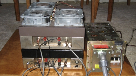
| The servo circuits were constructed on generic DIP circuit boards installed in the lower Dyna 120 power amplifier case. The lock LED is at the left. The phono connector for the video input is at the right and the DIN connector for the opto interrupter in the projector is below it. The modified Dyna 120 power amplifier sits on top with the added fans. Interconnetion between the two chassis are the phono cables left and right for the opposite polarity sine waves. Only two wires between each top red binding post and its mate are needed to connect the 40 Volts AC to the transformer in the lower chassis. The projector motor connects to an outlet on the opposite end of this chassis. The large chassis at the right is a surplus computer power supply. Its upper right connector supplies DC power to the servo chassis, and contains the large contactor that switches on the projector lamp only when the servo is locked. The projector wiring was changed, adding separate power cords for the motor and lamp. |
|
| Yes, that is a date. This film chain system was completed in 1996 and still works. |
| Demonstration of the Servo Locking |
| A video of the system locking and running is at CarlstromVideo on YouTube. In the video look for the lock LED to turn green and listen for the big contactor to pull in and light the lamp. Note there is no flicker in the movie image. As the projector starts, it is running faster than the video. The IR opto interrupter on the shutter is compared to video sync and the projector slows, undershoots, and then locks to the video. The big clack sound is the relay that turns on the lamp when the servo is locked. In the first demo, the lock indicator turns from red to green. The second demo shows the lock up on the screen. The third demo is with the room light off to see the film better. |
| Demonstration of the Results |
| A film transferred to video with this system is posted at CarlstromVideo on YouTube. |
| 30 Frames Per Second Minus 0.1% |
| On this page I've called the television frame rate 30 frames per second and the field rate 60. They are not. They are really 29.97 frames per second and 59.94 fields per second. In the 1940 NTSC standard it was exactly 30 frames per second. But the color update in 1953 made all the rates exactly 0.1% lower. 30 fps became 29.97 fps. The field rate changed from 60 to 59.94, and so on. This was done because the color sub-carrier had a beat frequency with the broadcast sound carrier. To minimize the visibility of that beat, either the sound carrier frequency had to change or the color sub-carrier had to be adjusted. The decision was made to move the color subcarrier 0.1% lower. Since it is synchronous with the horizontal and vertical scan rates, they moved as well. In hindsight, the sound carrier should have been the one to move as the consequences of the frame rate not matching the clock on the wall have created endless work for television practitioners since the change was made. |
Send questions or comments on this page to David Carlstrom.